Kleemann Crusher Mc140z Schematic Diagram - Automotive
Kleemann Crusher Mc140z Schematic Diagram Size : 950 KB Format : PDF Language : English Brand: Kleemann Type of machine: Crusher Type of document: Schematic Diagram Model: Kleemann Crusher Mc140z Number of Pages: 150 Pages Serial Number: K0610200. Related Products. Kleemann Crusher Ms14 Ms16 Ms19 Spare Parts Catalog.
Learn MoreFlowchart Diagram Of How Stone Crushers Work
From simple crusher flow diagram to complex crushing flowsheet, and it is an integrated work team with two mobile crushers Stone Crushing Plant; flow process diagram roofing |
Learn MoreSchematic diagram of a cone crusher (after [2] Figure 6.3
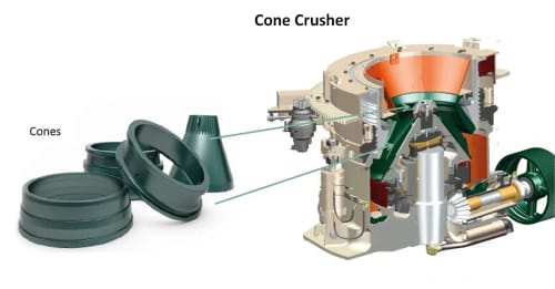
Figure 2 is a schematic diagram of a typical cone crusher. Material is introduced into the crusher from above, and is crushed as it flows downwards through
Learn MorePDF Qj341 Jaw Crusher Pioneering Solutions for YouPDF
QJ341 JAW CRUSHER PIONEERING SOLUTIONS FOR YOU TECHNICAL SPECIFICATION The QJ341 is the largest in the Q-Range of tracked jaw crushers. Utilizing 's unrivalled design and manufacturing expertise, it is one of the best-selling track mounted mobile jaw crushers in the world today. Featuring a powerful 1200 x 750 / 47" x 29
Learn MoreCrushing Plant Flowsheet & Design-Layout - Mineral Processing & Metallurgy

Before the advent of the cone crusher the usual practice was to make a 2-in. product in two steps consisting of a primary breaker of the jaw or gyratory type followed by a secondary gyratory crusher. If anything smaller were desired, a third stage was added comprising coarse crushing rolls in closed circuit with a screen.
Learn MoreJaw Crusher - an overview | ScienceDirect Topics
For a jaw crusher the thickness of the largest particle should not normally exceed 80–85% of the gape. Assuming in this case the largest particle to be crushed is 85% of the gape, then the gape of the crusher should be = 45.7/0.85 = 53.6 cm and for a shape factor of 1.7, the width should be = 45.7 × 1.7 = 78 cm.
Learn Morediagram of a rock crusher | Mining & Quarry Plant
2013. 3. 12. · Diagram Jaw Crusher | Crusher Mills, Cone Crusher, Jaw Crushers rock crushers diagram Lima. Ross. 1964 lima 500t truck crane, 50 ton, s/n 3444-8. 250 jaw dies & parts, very clean crusher & in good condition
Learn More2: Schematic illustration of a jaw crusher by J. Quist

Download scientific diagram | 2: Schematic illustration of a jaw crusher by This thesis focuses on developing models of crushers and equipment used in
Learn MoreCrusher Quick-Start Guide - OLCF User Documentation
The Crusher Compute Nodes diagram will be helpful when reading this section to understand which physical CPU cores (and hardware threads) your processes and
Learn MoreTorque Analysis of a Gyratory Crusher with the Discrete
A calculation procedure for the crushing power of crushers is presented, Schematic diagram of the primary crusher used in DEM simulation and the
Learn MorePDF Construction Working and Maintenance of Crushers for Crushing Bulk ...PDF
Construction detail and working of the crusher is as under. The main shaft of the crusher is journaled in the spider bearing and in the eccentric bearing assembly. The spider bearing fixes the position of the upper end of the main shaft. Eccentric bearing assembly with inner bushing can be replaced, or in some models turned, to adjust the stroke.
Learn More
Leave A Reply